1.2. More Figures, Less Text
These are figures used in other parts of this document. Is there any interesting topic for you?
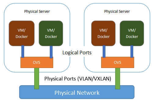
Physical View of the Network
This is the physical view of the SDN network. VMs or containers are in different servers, but we want to organize them in a logical way. See Physical View of the Network.
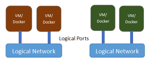
Logical View of the Network
This is the logical view of the same network. VMs or containers are organized by their logical positions; their physical positions do not matter. See Logical View of the Network.
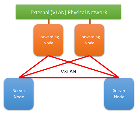
L3 Network with Forwarding Nodes
This is a network with forwarding nodes. A forwarding node forwards traffic between SDN networks and traditional networks. In VLCP, the forwarding nodes are just normal SDN controllers with a few configurations turned on. See L3 Network with Forwarding Nodes.
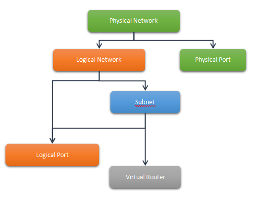
Network Settings Structure
This is how we configure our SDN network. See Network Settings Structure.
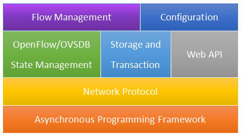
Technology Stack of VLCP
This is the technology stack of VLCP - how this software is built. See Technology Stack of VLCP.
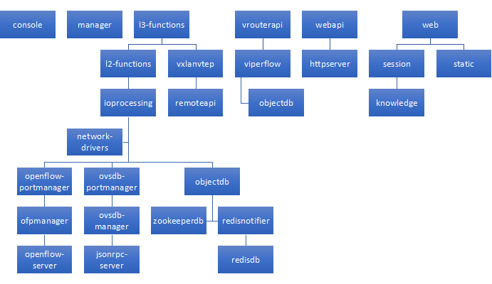
Modules of VLCP
This is the current modules and relationships between them. See Modules of VLCP.
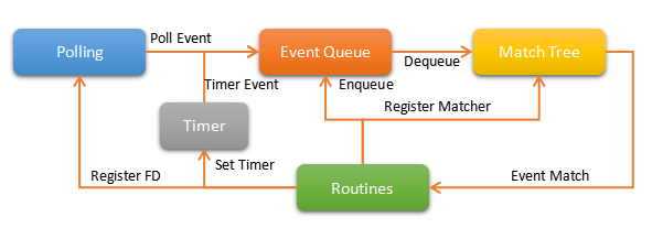
Scheduler Work Flow
This is the design of the core scheduler of VLCP, it provides asynchronous programming interfaces for this software. See Scheduler Work Flow.
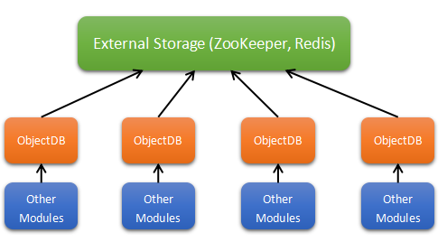
Central Storage
This is the architecture of the central storage system. VLCP uses an external KV-database for data storage, any nodes can read from or write to the central database independently. A transaction layer - ObjectDB is used to synchronize these operations. See Central Storage.
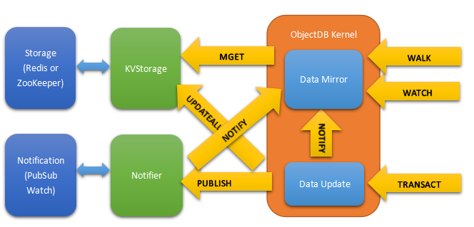
ObjectDB Basic Design
This is the design of ObjectDB. See ObjectDB Basic Design.
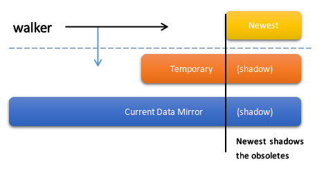
Isolation of Data Space for walkers
This is the description of isolations for walkers. ObjectDB uses a special way - walker function to describe a reading transaction, and uses updater function to describe a writing transaction. This provides a very flexable and easy way to use the transaction. When executing a walker, VLCP uses this technique to provide consistent data for the walkers. See Isolation of Data Space for walkers.
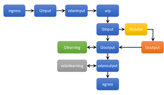
OpenFlow Tables
This is the currently used OpenFlow tables in VLCP. See OpenFlow Tables.